The Quaduino quadruplex system consists of four individual computing lanes that synchronize and and exchange data.
Single Computing Lane
Each computing lane consists of an Arduino Mega2560:
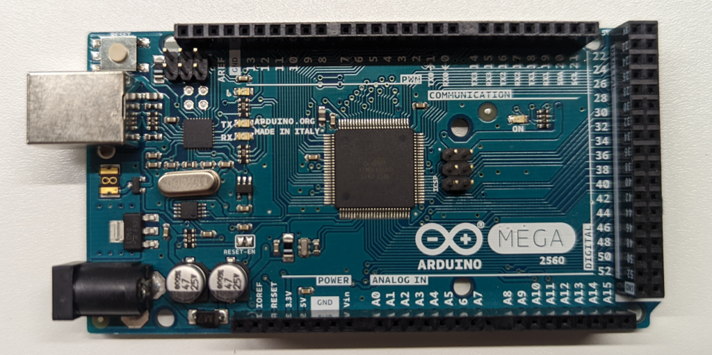
The software is flashed on each single lane and in principle each computing lane can perform its own services. To allow redundant execution of functions, the lanes have to communicate with the three other lanes, the so-called cross-lane-communication.
Cross-Lane-Communication
The lanes communicate via dedicated RS485 busses: each lane has a dedicated sender-bus that connects to receiving ends on each other lane. We use simple RS485 daughter boards:
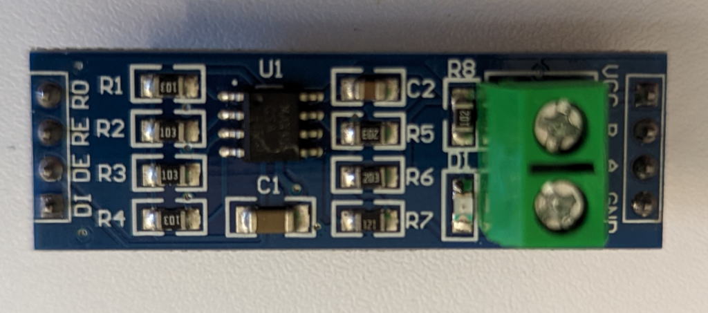
A student of mine designed a PCB that can hold four of these and connect them to the suitable ports on an Arduino Mega 2560:
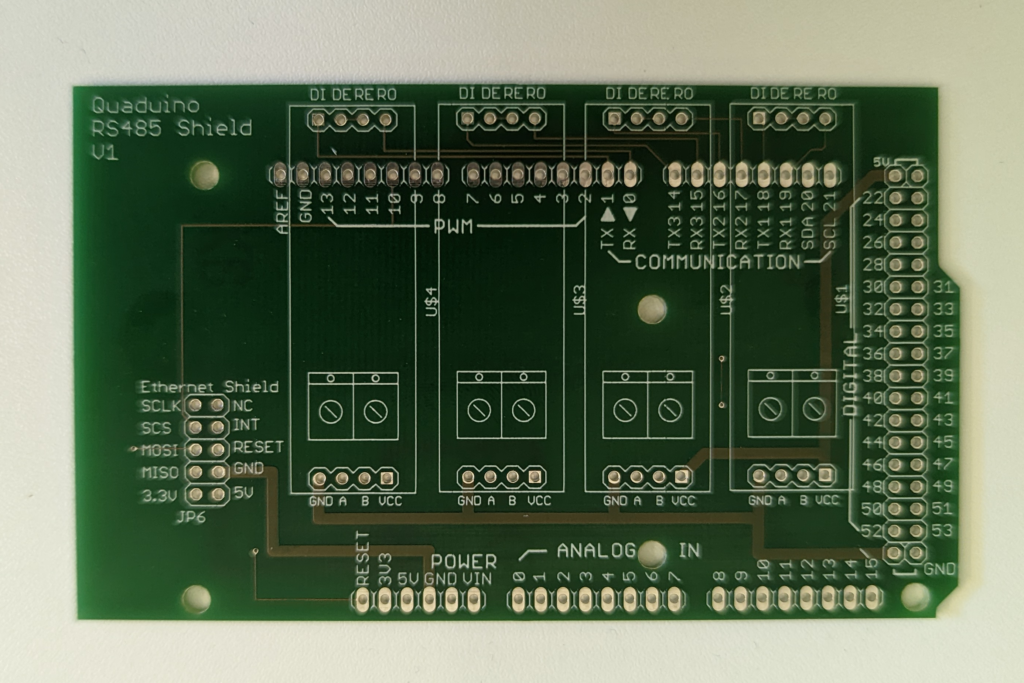
The port marked U$4 (left-most) connects to RX0/TX0 and is the designated sender port. A full single lane consists then of the Arduino Mega, four RS485 boards, an Ethernet board and this shield.
Ethernet-Capability
To enable a centralized combined debugging-option, each lane sends its internal data via Ethernet to a central server. We opted for the W5500 Ethernet Shield:
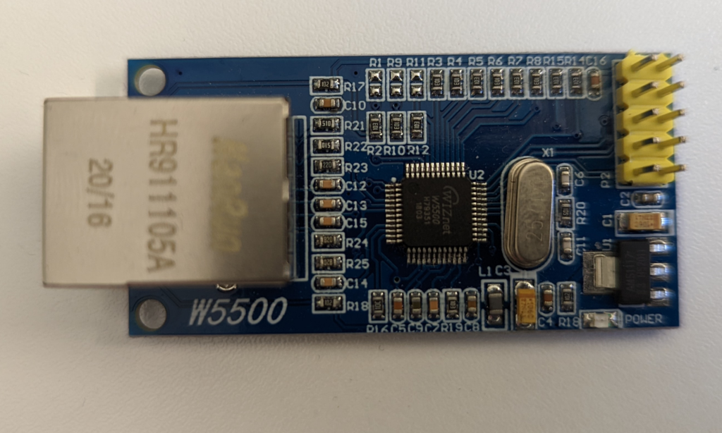
It sits on the area marked „Ethernet shield“.
Assembly
The assembly including all cables looks like this:
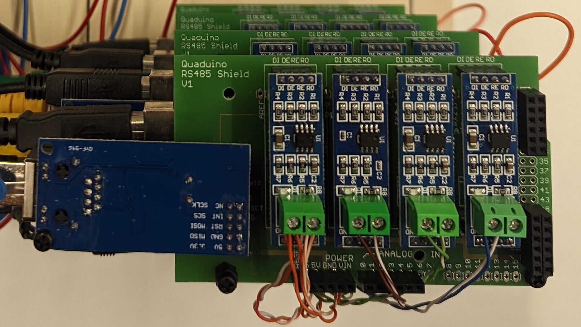
As you can see, the sending RS485 module has three pairs of cables and each receiving module has only one pair of cables. Orange cables designate lane 1 sending, brown is lane 2 sending, green lane 3 sending and blue is lane 4 sending.
Schreibe einen Kommentar