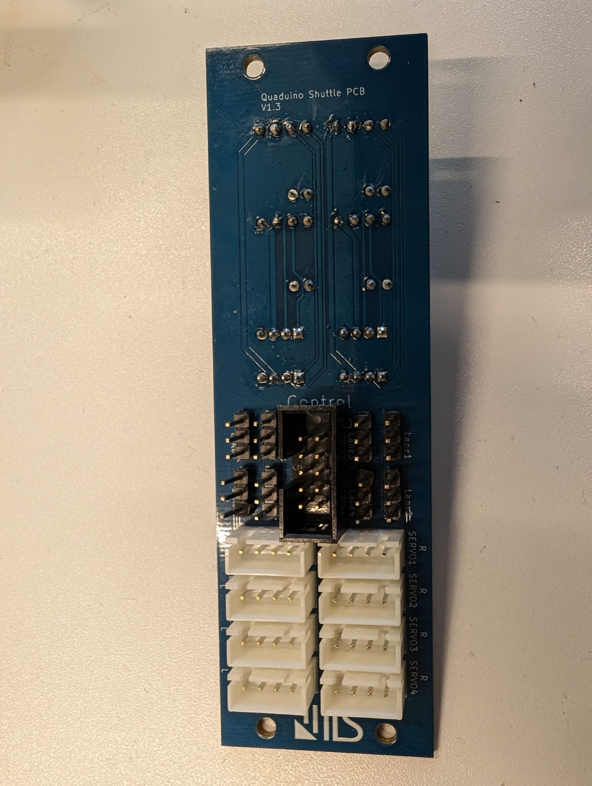
After redesigning the shuttle airframe, the next bottleneck was wiring and maintainability. Our answer: a custom Shuttle PCB that brings power, sensors, and actuators into the shuttle model.
Why We Built Our Own Board
- Reduce cabling complexity and assembly time
- Provide stable, well-documented power rails and protections
- Standardize connectors for sensors, servos, and peripherals
- Improve reliability under demo and classroom conditions
What’s on the Board
- Connectors for each Quaduino lane to the shuttle
- Connectors for 4 time-of-flight (ToF) distance sensors — one sensor per lane
- Connectors for 8 servos to move the elevons — two servos per lane
- Connector for servo-position feedback to the control Arduino (environment simulation)
Reliability in the Real World
We built for the realities of outreach and events:
- Quick swap: modular mounting and connectors enable 5–10 minute board/sensor/servo swaps.
- Label-first design: port labels and physical layout match the hardware connectors.
What This Enables
- Faster setup for Mini-Shuttle kits
- Demonstrations in System Design I
- Sensor and Actuator Lab Course for System Design II
Lessons Learned
- The first PCB never works correctly.
- Too many cables make everything hard.
- Custom PCBs make it a bit easier and more consistent.
Schreibe einen Kommentar